
We take for granted the fact that an electric cell (or battery) will cause a current to flow through an external circuit. The current is often discussed in terms of a flow of electrons (like water through a pipe) or energy transferred between adjacent electrons (like a row of dominoes falling onto each other). It might even be explained in terms of the action of an electromagnetic field (the Poynting vector). But all of this happens in the external circuit: what is going on inside the cell itself?
Electrical cells work through the combined effect of two chemical reactions; one is an oxidation reaction, the other is a reduction reaction. As the old chemistry mnemonic “oil rig” states; oxidation is loss, reduction is gain. The loss and gain refer to the transfer of electrons. So in an oxidation reaction, electrons are liberated; in a reduction reaction, electrons are captured. The way that electrons travel between the oxidation and reduction reactions in an electric cell is via the external circuit and the voltage generated by the cell is equal to the difference in potential between the two half-reactions (oxidation and reduction).
In an old-fashioned zinc-carbon cell, the oxidation reaction is the ionisation of metallic zinc (to form zinc chloride) and the reduction reaction is…. nothing to do with carbon! It is true that there is a carbon rod but this simply makes contact with the reduction reaction, which involves converting manganese dioxide into a different form of manganese oxide. Specifically, manganese (IV) oxide is converted into manganese (III) oxide.
The link between these two reactions is provided by an electrolyte. In traditional zinc-carbon cells the electrolyte is damp ammonium chloride, which is acidic and over time will corrode the zinc casing, causing the cell to leak. In years gone by, zinc-carbon cells had a mercury coating to stabilise the zinc and reduce leakage but environmental concerns led to its removal. In newer cells, the electrode reactions are kept the same but the electrolyte is potassium hydroxide, which is alkaline – hence the name “alkaline cell”.
Although both types of cells have a nominal rating of 1.5 V, the exact figure varies slightly. In theory it is determined by the electrode potentials of the two half-reactions but real-world battery chemistry is rarely that simple. In practice, fresh cells can have terminal potentials up to 1.6 V or even slightly higher but this could drop to 1.2 V under load. The fact that near-identical cells can differ so much in their output means electrical circuits are required to have a degree of voltage tolerance and this in turn explains why different types of cells with different half-reaction potentials can be used in the same application even when their nominal voltages differ (see https://www.electrical4u.com/alkaline-batteries/ for more details).
Alkaline cells have a higher energy density (last longer) than traditional zinc-carbon cells and also have a more stable voltage, both during use and over the course of their lifetime. In all cases, the maximum terminal voltage is obtained when there is zero current being drawn from the cell. In a fresh cell, the maximum terminal voltage is equal to the cell’s EMF (which is fixed) but more generally it varies with use and is referred to as the open-circuit voltage (OCV).
To complicate matters further, the working voltage of a cell depends on the magnitude of the external (load) resistance. This is because the cell has its own internal resistance and the total cell voltage is split between the internal and external resistances according to their proportions. With high external resistance, the current is small but most of the cell energy (voltage) is transferred to the external circuit; lower external resistances increase the circuit current but reduce the measured voltage.
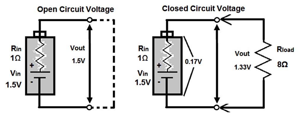
Internal resistance arises from both electrical and electrochemical effects; the former are instantaneous and include the quality of connections and the resistivities of the materials used whereas the latter accumulate and are due to factors such as electrolyte conductivity and electrode surface area. According to various data sheets issued by Energizer, the internal resistance of a fresh alkaline cell is expected to be in the range 150 – 300 mΩ. For more details, see https://data.energizer.com/pdfs/batteryir.pdf, https://energizer.com/wp-content/uploads/2025/01/e91_max_na.pdf, https://energizer.com/wp-content/uploads/2025/01/ENR-max-aaa.pdf and https://data.energizer.com/pdfs/alkaline_appman.pdf.
As well as varying with cell geometry, internal resistance also varies with the test method used, the ambient temperature and the condition (state of charge) of the cell, as illustrated below.
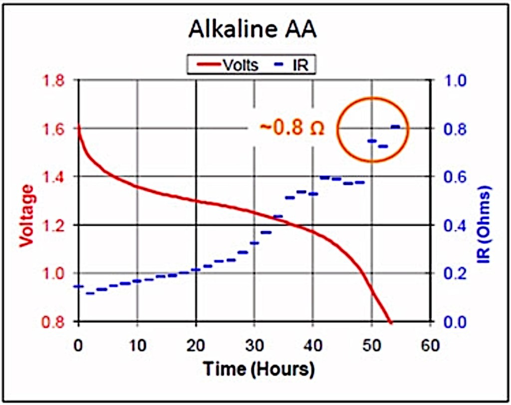
Needless to say, internal resistance also varies with cell chemistry and it is for this reason that some types of cells, zinc-carbon in particular, are unsuitable for high-drain applications as they simply cannot deliver a sustained high current. Rechargeable cells tend to do better in such applications.
As mentioned above, most devices are designed to operate with cells rated in the range 1.2 V – 1.5 V, which not only covers single-use cells but also fits well with nickel-metal-hydride rechargeables that start at about 1.4 V when freshly charged and operate at around 1.2 V throughout most of their useful life. There is a great summary of this, together with links to more battery information at https://www.electricity-magnetism.org/electric-battery/characteristics-of-aa-batteries/ and at https://www.eblofficial.com/blogs/battery-101/nimh-battery-voltage.


