There is a summary of the key characteristics of astronomical telescopes in a previous post, at https://physbang.com/2026/03/15/a-level-guide-to-astronomical-telescopes/. This article builds on that general overview by explaining a specific skill; how to draw a ray diagram for a refracting telescope in normal adjustment.
First, what is “normal adjustment”? It is when the objective and eyepiece lenses are arranged so that the image viewed through the eyepiece appears to be at infinity. This is useful as the eye is most relaxed when focused “at infinity” so normal adjustment provides the most comfortable viewing conditions.
The fact that the image is viewed “at infinity” means the light rays leaving the eyepiece lens must be parallel to each other. That in turn means the light rays must originate from a point located at the focal length of the eyepiece lens.
Similarly, the light rays entering the objective lens at the front of the telescope are also parallel because they have originated from an object so distant that we can regard it as being “at infinity”. Using the same logic as applies to the eyepiece lens, the parallel incoming rays must come to a focus at the objective lens’s focal length.
Therefore, when a telescope is in normal adjustment, the focal point of the objective lens must coincide with the focal point of the eyepiece lens, meaning the total length of the telescope will be equal to the sum of the objective and eyepiece focal lengths. The overall length of a refracting telescope, together with image magnification for any type of telescope, were amongst the points covered in the previous post.
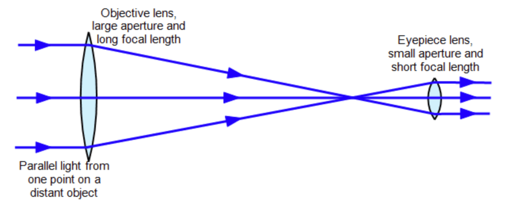
A simple diagram of normal adjustment, based on axial rays (light rays that are parallel to the principal axis of the two lenses) is shown below.
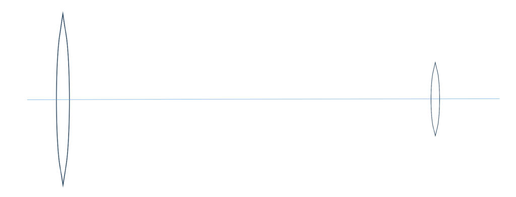
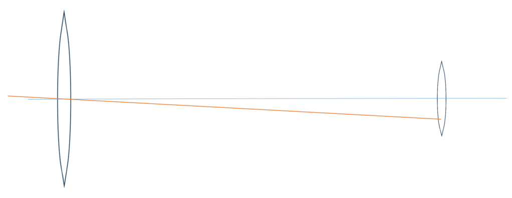
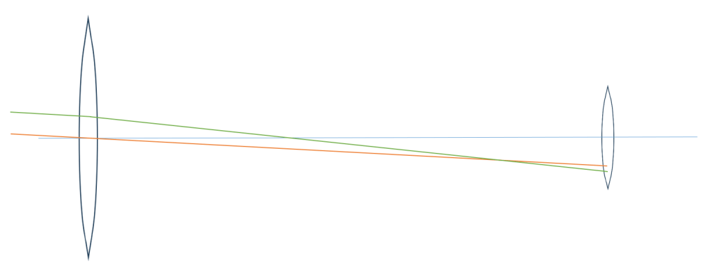
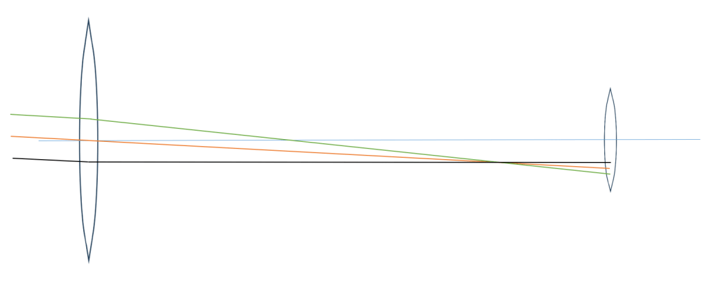
Unfortunately, A-level exam questions often require the normal adjustment diagram to be drawn using three non-axial light rays. This requires a bit more thought than when axial rays are used but the method is fairly easy provided the task is approached in a systematic way. The various steps required are shown in the sequence below.
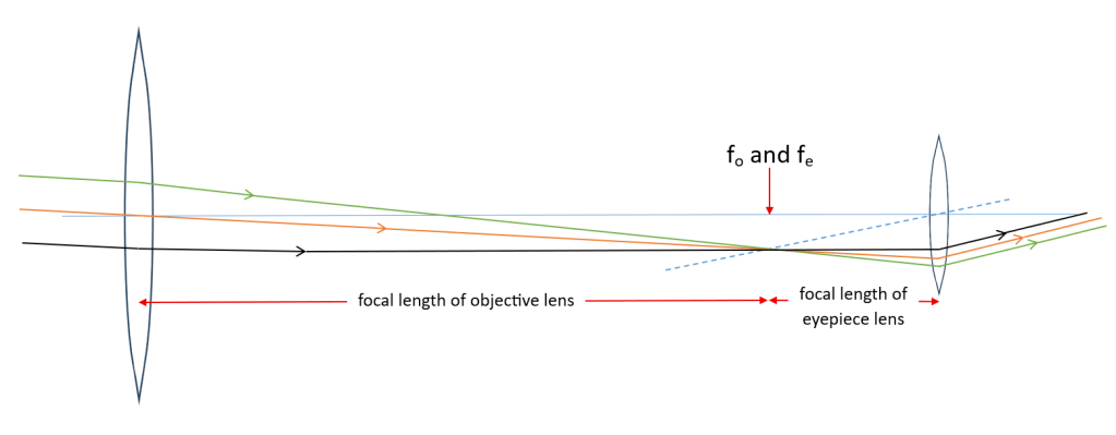
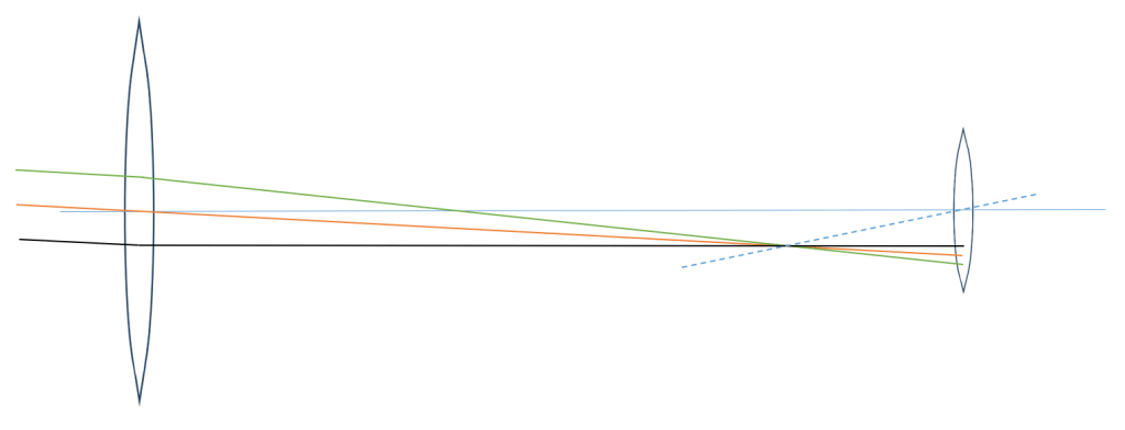
To complete the diagram we need to add the parallel rays that emerge from the eyepiece lens. But first we need to know the correct angle for the emerging rays. This is done using the fact that there will be a certain ray coming from the focal point of the eyepiece lens that passes through the eyepiece undeflected. This is not one of the light rays required – but it shows the correct angle. The emerging rays can then be added, parallel to the guidance ray.
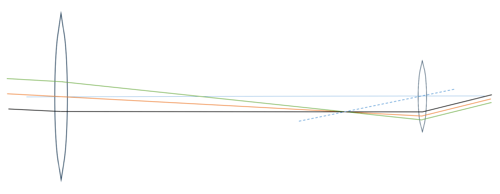
The final step is to label the intersection as the focal point for both the objective lens and the eyepiece lens. Alternatively, depending on the wording of the question, it might be necessary to label the focal lengths of the two lenses. These variations are shown in the diagram below, which also has arrows to indicate the direction of the light rays.