
Having previously discussed micrometers as instruments that some people find tricky to read (see https://physbang.com/2025/04/09/how-to-read-a-micrometer/) we now come to the instrument that many people find even more difficult; Vernier callipers.
Whereas micrometers are mostly used for measuring thicknesses between flat surfaces, callipers are better when the surfaces are curved. In particular, callipers are commonly used when measuring the inside diameter or outside diameter of a tube or washer. There are digital versions (of course) but the ability to read the scale on a pair of analogue callipers is a particular technique that the examination board expects you to have mastered.
Analogue callipers (or calipers, in American spelling) use two scales, one of which is more compressed than the other. In the diagram below, the 10 divisions of the smaller (fine-measurement) scale are the same length as nine divisions on the main scale. The theory behind the design isn’t required for A-Level Physics but it’s worth noting that the idea was first announced by the French mathematician Pierre Vernier in 1631 as a way to measure angles with a higher resolution than had previously been possible. It is a really clever system and Vernier deserves a much higher profile than he has been given in the history of science.
Note that the diagram below shows a mock-up of analogue callipers created using a paper template that has an expanded scale, which is easier to read than the scale on real-life Vernier callipers. Being paper-based it’s not a precise instrument but it’s very useful for explaining the appropriate method.
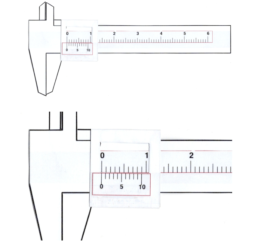
You will see that the zeroes on the top and bottom scales are exactly aligned with each other and that none of the other markings line-up except for the last one, labelled 10, on the lower scale. This tells you that the callipers are set to zero and there is no zero error.
Looking more closely at the enlarged image, you should notice that the misalignment between the marks on the top and bottom scales gets progressively greater moving to the right, away from the zero on the bottom scale, then reduces until there is perfect alignment again at the 10 mark. The fact that all the other markers are misaligned tells you these markers are irrelevant for determining the correct reading of the scale, which is always defined by the two markers that are perfectly aligned (or the ones that are closest to being perfectly aligned).
Let’s look at a non-zero setting (again using the cardboard mock-up) to see how the technique is applied to make an actual measurement.
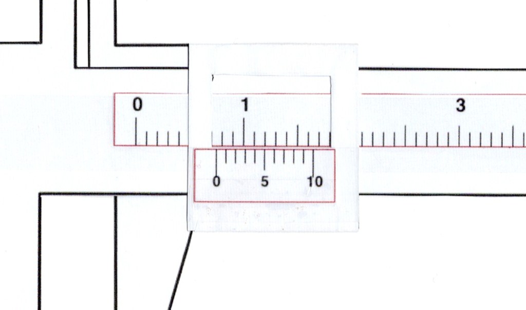
To read the callipers, first determine the value on the main (full-length) scale. This is indicated by determining the position of the zero on the fine-measurement (short) scale. In the example above, the zero sits about half-way between 0.7 and 0.8 on the main scale, so we know the measurement will be in this range – and probably has a value of about 0.75.
We then look to see which value on the fine-measurement (short) scale has its marker perfectly aligned with one of the marks on the main scale. In this case it is the 5 line. You should notice that the previous line on the fine-measurement scale sits just after the nearest ruling on the main scale whereas the next line sits just before the ruling that is closest to it. So the 5 line is the “turning point” and that means it represents the best alignment, giving a final value of 0.75 for this measurement.
One more example using the mock-up callipers should be enough before we look at real-life Vernier callipers.
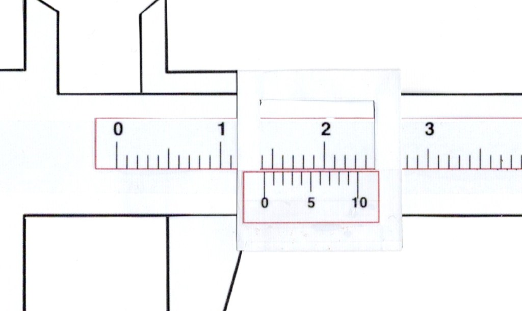
To determine the second decimal place, look to see which mark on the fine-measurement scale is best aligned with any mark on the main scale. In a real-life situation, it is often helpful to use a magnifying glass (hand lens) to examine the scale more closely, bearing in mind that there may be NO marks that are exactly aligned and you could be forced to make a judgement about the best alignment that can be seen.
In the diagram above, the second division on the fine-measurement scale (after zero) has the best alignment with the main scale. The first division is slightly to the right of the closest mark on the main scale whereas the third division is slightly to the left of its closest mark on the main scale. Therefore, the second division, indicating the number 2, is the correct value to choose, giving a final measurement of 1.42 for this particular example.
Exactly the same method is used when reading real-life Vernier callipers, an example of which is shown in the photograph below.
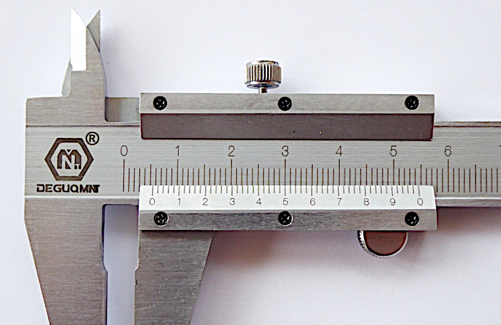
The position of the zero on the fine-measurement scale, when read against the main scale, indicates that the measurement being made has a value between 5 mm and 6 mm (0.5 cm and 0.6 cm). We can also see that the zero mark is probably slightly less than half-way between these two extremes, suggesting a measurement of about 5.4 mm.
Looking at the numbered divisions on the fine-measurement scale, it is clear that 4 is very slightly to the right of the nearest mark on the main scale and 6 is to the left of its nearest main-scale mark by a similar amount. So the measurement will be greater than 5.4 mm but less than 5.6 mm.
At this point, judgement (and maybe a hand lens) comes into play. If you enlarge the image on your screen, you may decide that the best alignment corresponds with either the 5 marker on the fine-measurement scale or maybe the first division after the 5. It also looks as if the third division after the 4 could be perfectly aligned but this cannot be a true reading because the divisions to each side of it both sit to the same side of their nearest main-scale markings.
If the 5 marker is most accurately aligned then the final measurement is 5.50 mm but if the first division after the 5 marker has the best alignment then the final measurement will be 5.52 mm. Note that the first measurement has a trailing zero: writing 5.5 mm would be wrong because it doesn’t express the full resolution offered by the Vernier scale.
You also need to state the uncertainty, which is +/- 0.01 mm for this instrument. If you fail to do this then somebody might assume that giving a second decimal place implies a resolution of +/- 0.005 mm, which is clearly not the case given the markings visible on the fine-measurement scale. (* see below)
Finally, it is important to stress that parallax is very important when reading the scale on Vernier callipers. A photograph (as above) has to be taken from a single viewpoint but you need to keep your eye perpendicular to the scale at all times when trying to identify the best alignment. This means you MUST move your head: it is not possible to identify the best alignment across an extended scale if you keep your head in one place and simply track your eyes from side to side.
* These figures were corrected on 21st April 2025 as they were originally stated without halving (+/- 0.02 mm and +/- 0.01 mm respectively).

One thought on “How to read Vernier callipers”