
Being able to take measurements using common items of instrumentation is an expected skill for A-Level Physics and can be tested in examinations using diagrams or photographs.
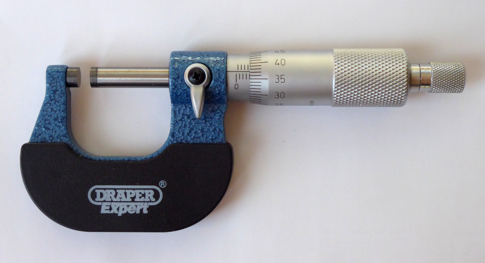
This post is the first in a short series that will look at measurement skills, starting with a piece of equipment that often causes difficulties; the micrometer. To be more exact, we are looking at the type of micrometer that is used to make external measurements between flat surfaces, or of wire diameters, up to a maximum thickness of 25 mm.
The traditional design, shown in the picture below, has a manual scale and a maximum resolution of 0.01 mm. Using the usual convention of taking half the interval range, this micrometer has an uncertainty of +/- 0.005 mm. (Digital micrometers are a bit different so they will be covered in a separate post.)
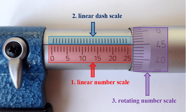
To determine a measurement using an analogue micrometer it is necessary to read three separate scales and to sum their values to obtain the correct reading.
- Read the value on the linear numbered scale
- Read the value indicated by the dashes on the unnumbered scale
- Read the value on the rotating numbered scale
These three scales are identified in the photograph below, where the entire linear scale has been made visible for clarity – although this would never be the case when taking actual measurements.
To combine these values correctly it essential to understand what each scale indicates. We will cover the general method first then look at some examples.
1. The linear numbered scale measures whole millimetres. The right-most visible mark indicates the number of whole millimetres in the measurement so it gives the value that is to the left of the decimal point. Only every fifth mark is numbered so you must count up from the closest numbered value to determine the value corresponding to the mark that is closest to the rotating collar.
2. The linear dash scale indicates half-millimetres. It only comes into play when there is a visible dash that is closer to the rotating collar than the last whole-millimetre mark. A visible dash indicates that the measurement is in the second half-millimetre. For example, if the right-most whole millimetre mark is “5” and there is also a dash clearly visible then the measurement will be equal to or greater than 5.5 mm.
3. The rotating scale provides the detail for the half-millimetre range. It is marked from 0 to 49 and is read by taking the value that lines-up with the axis line separating the two linear scales. When there is no dash visible immediately to the right of the number mark, the rotating scale gives the figures that come after the decimal point. If there is a dash visible then the number on the rotating scale must be added to 50 to give the value after the decimal point. For example, if we have our 5.5 from the two linear scales and the rotating scale has 45 against the axis line then the value after the decimal point will be 50 + 45 = 95, giving a final measurement of 5.95 mm.
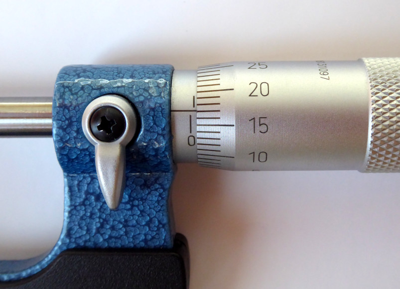
So much for the theory: let’s look at some examples.
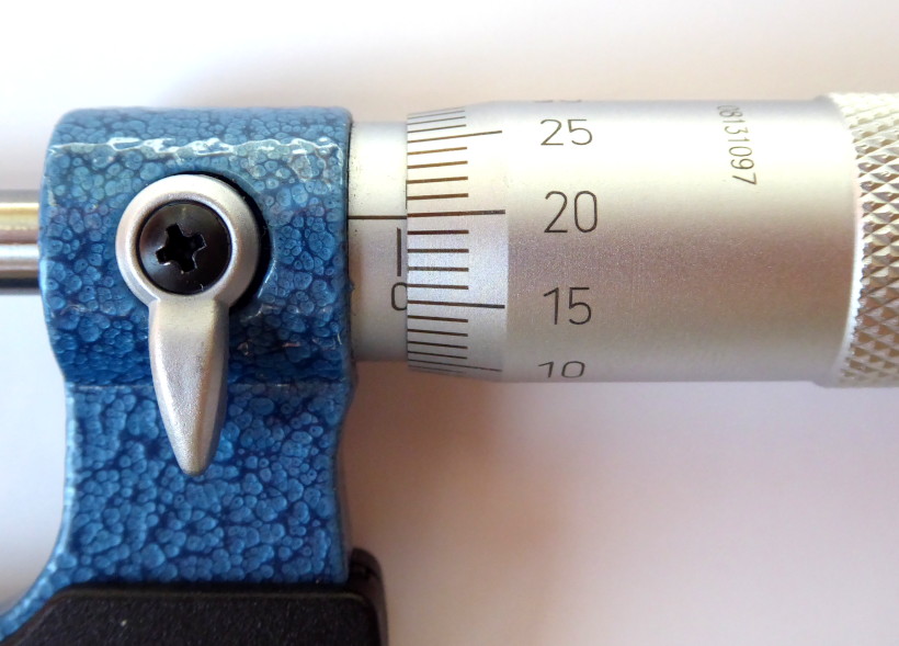

Note that if we had (wrongly) included the half-millimetre mark in the last example then our measurement would have been 4.93 mm. This is very nearly 5 mm – and that clearly doesn’t match with having the half-millimetre mark only JUST visible. You need to be very careful when dealing with the half-millimetre mark as it is easy to misinterpret the values.
To test your understanding, I have created two self-marking online tasks that are hosted at liveworksheets.com. The first task just involves reading displayed values, as explained above. The second worksheet requires you to take account of the micrometer’s zero reading before you determine the true measurement.
To enter an answer, just click on the box and type away. You can check your answers privately or you can submit your work to me (you will also get to see the results yourself immediately). When submitting work to me, use the code bs3L6RTopb instead of my usual email address.
To access the first worksheet, click here or enter the following address in your browser’s address field… https://www.liveworksheets.com/c?a=a&sr=n&l=kp&i=oznffcx&r=qm&f=dzdfzczn&ms=uz&cd=dlchjgleekmtvngnegkglxg&mw=hs
To access the second worksheet, click here or enter the following address in your browser’s address field… https://www.liveworksheets.com/c?a=a&sr=n&l=vt&i=oznfssu&r=oz&f=dzdfzczn&ms=uz&cd=dlyzjgleppxjgngnegkglxg&mw=hs
Don’t forget to use the code bs3L6RTopb if you choose to submit your work to me.

2 thoughts on “How to read a micrometer”