
Electricity is one of the forms of energy transfer so it is not surprising that the definition of the volt (the unit for measuring potential difference) is the energy carried per unit charge. In symbols, where Q is the symbol for charge, this relationship is written as;
V = E / Q
It is important to realise that the above relationship is actually a definition rather than a simple equation. In this year’s equations hand-out for AQA Trilogy examinations, the relationship is shown as E = V Q with energy as the subject of the equation, emphasising the fact that the flow of electricity is a transfer of energy.
As mentioned above, Q is the symbol for electrical charge, which is measured using a unit called the coulomb (which has the symbol C – and that is why the symbol Q has to be used to represent charge).
You can think of charge as measuring the number of electrons that flow through a circuit. If a lot of electrons move through a circuit then a lot of energy will be transferred. The rate of electron flow in a circuit is called the current, which is represented by a capital I (remember that the letter C has already been taken). Because it is a rate, the equation for current involves dividing by time: effectively, it is how many electrons pass a point in the circuit each second.
I = Q / t
A high current means lots of electrons are going around the circuit, carrying lots of energy. To increase the energy even more, we can increase the potential difference (voltage) as this determines how much energy each electron will carry. In fact, these two equations can be combined to give one ‘super equation’ that expresses electrical energy in terms of potential difference and current, without any need for charge.
This is useful because we can measure potential difference (voltage) and current using simple meters, making it easy to calculate the energy transferred by an electric circuit. All we have to do is multiply the potential difference and current by the time for which the circuit is being used. But the time must be in seconds! Watch out for that because an examination question could give you the time in minutes and you must remember to do the conversion.
E = I V t
The above equation is not in the AQA Trilogy hand-out so it would only be used indirectly in a multiple-part question in the Higher Tier paper, where you would probably get to the final answer by working out a couple of separate stages first. For example, you could be asked to calculate the power of a circuit using P = I V (which is on the equations sheet) then to find the energy by using E = P t (which is also on the sheet). You can see that if you substitute I V into the second equation in place of P then you will get the energy equation given above. Physics can be really neat sometimes!
Let’s leave equations, which you don’t need to memorise for the AQA Trilogy examinations this year, and look at something that you DO need to remember, circuit symbols. Here are the ones you need to know;

It is important to note that there are two different symbols for a switch, one open and one closed. This means that if you are asked to identify a switch symbol in a circuit then you must say whether it is open or closed. There will be no mark just for writing “switch”. This hasn’t come up for a while and I think it’s about due to reappear so watch out for that potential pit-fall! Note also the difference between a cell, which has a low voltage, and a battery, which has a higher voltage.
In many cases, circuit components are joined together in a chain to make a loop: a complete loop is the simplest type of electric circuit, called a series circuit. In this situation, there is just one way for the electrons to carry energy out of the battery and around the circuit – and that is by passing through each of the components in the circuit in turn. As they do that, the electrons transfer their energy to the components. We assume that wires and meters don’t take any of the energy so all the energy transfers are done by things like resistors (that get hot) and lamps (that emit light).
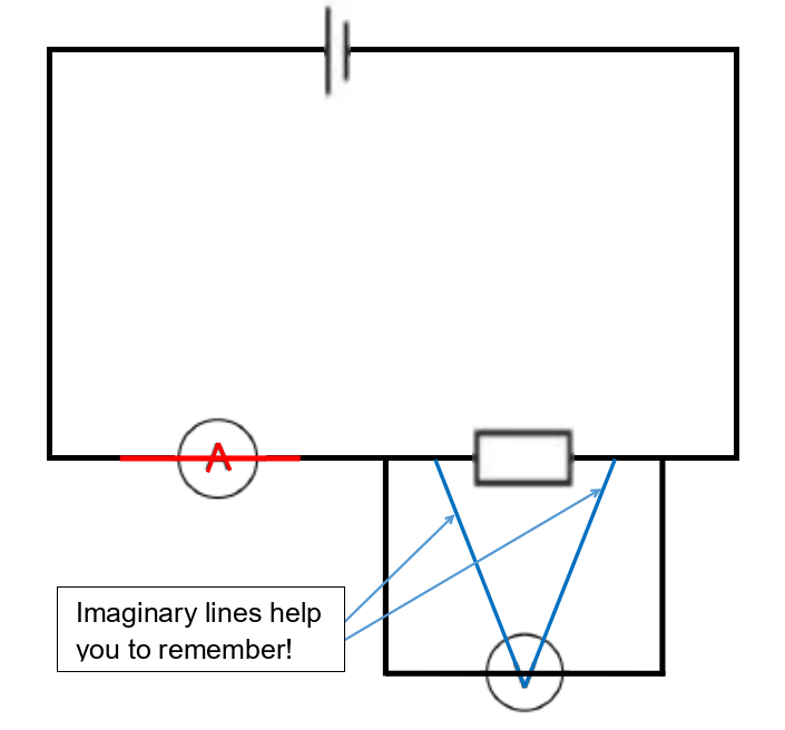
People often forget the proper way to connect meters in circuits but there is a useful trick you can use to help you remember. The official explanation is that voltmeters always go in parallel whereas ammeters go in series – but that isn’t very helpful if you can’t remember what those terms mean! Fortunately, you can look at the component symbols for a clue…
If you extend the V of the voltmeter symbol you get two “leads” that need to be connected to different sides of a component because they point in different directions. And if you extend the line in the middle of the A in an ammeter symbol it will join straight on to the lines (wires) to each side of the circle, so an ammeter can be drawn straight over the wires of a circuit but a voltmeter has to be outside the circuit. These two tricks are illustrated below.
We will come back to series and parallel circuits at the end of this article but before that we need to review some key facts about resistance, which is the mechanism by which electrical energy is transferred as heat and, in some cases, light. It can also be transferred as kinetic energy using a motor, the circuit symbol for which has a capital M inside a circle. The energy and power calculations explained above apply in exactly the same way to electric motors as they do to resistors and lamps.
You can calculate the resistance of any component, or even just a length of resistance wire, by measuring the current that flows through it and the potential difference (voltage) across it. You should immediately spot that this is a situation where you would be expected to know how to connect the meters correctly! When you have the meter readings, in volts and amps, you then use the following equation to calculate resistance;
R = V / I
The hand-out sheet lists the resistance equation as V = I R but this is the same thing and you will probably be expected to rearrange it to get the format shown above.
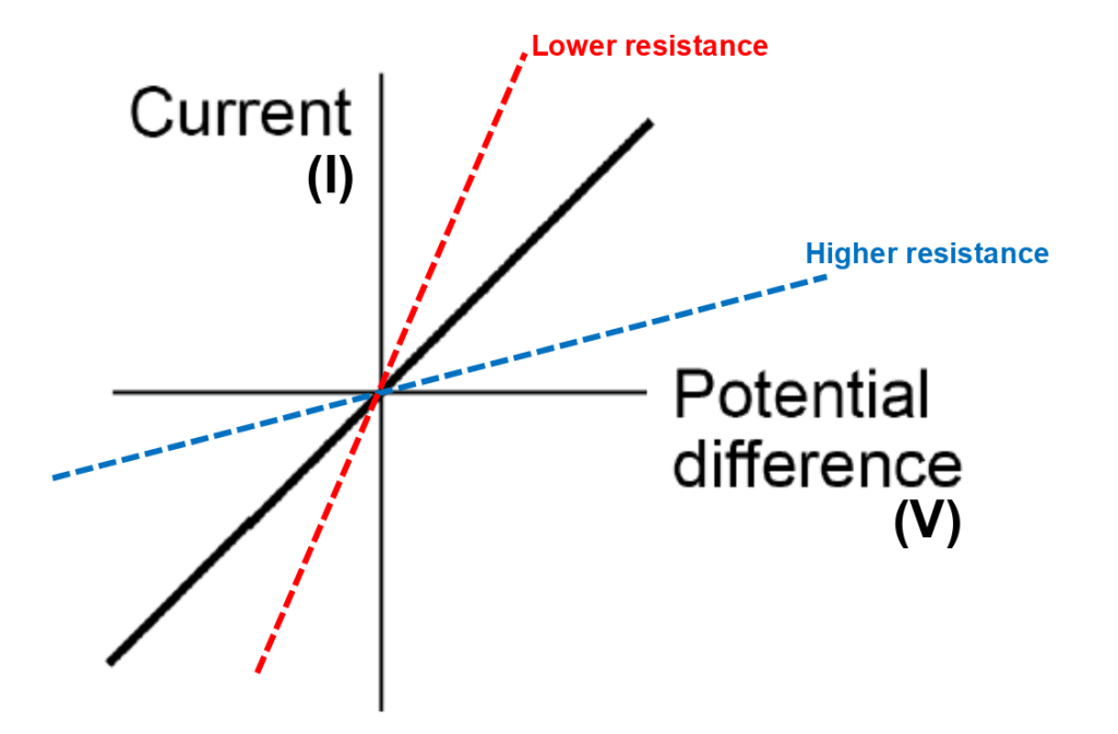
Ordinary resistors have a fixed resistance or one that can be varied manually and then stays constant. This means that the current-voltage graph for a fixed resistor has a straight line. A steeper line means a lower resistance, and vice-versa. Remember this fact because you could be asked to add a line to a current-voltage graph to show the behaviour of a component that has a lower (or higher) resistance than the one already shown, as indicated below.
You also need to know the resistance behaviour for two other types of components; filament lamps and diodes. We will come to the graphs for these two components in a moment but first we need to understand a bit about their behaviour…
A filament lamp is a light bulb that has a thin wire inside: the wire has high resistance so transfers lots of energy and gets so hot that it starts giving out light, by glowing. As it gets hotter, its resistance changes. Helpfully, the line that you get on the current-voltage graph for a filament lamp looks a bit like an italic f, with the line through the middle being the x-axis, so it’s easy to remember its shape because f stands for filament (lamp)!
A diode will only let current flow one way. This is indicated by the arrowhead in the diode circuit symbol. (Scroll back to the circuit symbols to see what I mean.) The current can’t flow the other way because it will hit an imaginary ‘brick wall’, shown by the vertical bar in the diode symbol. This means that, like its circuit symbol, a diode’s current-voltage graph is not symmetrical and that makes it easy to identify in a multiple choice question. As an added detail, even when the voltage is driving the current the right way through the diode, the current still loses a bit of energy (think of it as having to put in effort to open a one-way door in the wall) and this means the upward part of the line starts a little way along from the origin of the axes.

You must also be able to give a brief description of the resistance of two components that change their behaviour in response to changes in the environment around them. And you must abe able to suggest ways in which this behaviour could be useful. Here is a quick summary of what you need to know;
A thermistor changes its resistance when the temperature changes (the start of its name, therm-, is the clue here). When the temperature goes down, a thermistor’s resistance goes up. Thermistors can be used in thermostats to set the temperature of an oven or to keep rooms at the optimum temperature and prevent energy from being wasted if the room were to get hotter than it needed to be.
A light-dependent resistor (LDR) does what its name suggests; it changes its resistance depending on the amount of light in the surroundings. Like a thermistor, an LDR’s resistance goes down as the surroundings go up – but in brightness this time. Unsurprisingly, LDRs can be used to switch-on lights automatically when the surroundings get dark (at night) and, of course, to switch them off again when the surroundings get bright (during the day). Once again, this is an example of electronics being used to reduce waste energy by avoiding having lights switched on when they aren’t needed.
Finally, there are the two types of electric circuits that you need to be able to recognise and analyse.
The simplest is a series circuit, which has already been mentioned, and is where every component is connected in the same loop going from one side of the energy source (cell or battery) to the other. In series circuits, the current is the same everywhere because there is only one way for the electrons to carry their energy around the circuit.
But the potential difference in a series circuit can be different across different components. If a circuit has multiple resistors, or a resistor and a lamp, then you will find that adding up the potential difference across each component will give you the same value as the potential difference across the battery. This should not be surprising because the battery is supplying energy and the resistors are using the energy, and the two figures must always be the same. This is known as the conservation of energy. Put simply, total energy in is equal to total energy out.
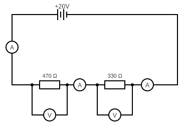
In the circuit above, the readings on all three ammeters would be the same and the readings on the two voltmeters would add up to give 20 V, which is the potential difference (voltage) of the battery.
The total resistance of a series circuit is the same as the sum of the resistances of the individual components and we can use this fact to work out what the readings would be on all the meters;
- first we work out the total resistance as the sum of the two resistors, which is 800 Ω
- then we notice that the potential difference supplied to the circuit is 20 V
- this means we have a resistance and a potential difference, so all we are missing is the current…
- select the right equation; V = I R (from the equation sheet)
- rearrange to make current the subject; I = V / R
- substitute values to give I = 20 / 800
- calculate the answer (with units): I = 0.025 A
We know that the current is the same everywhere so all three ammeters must read the same value of 0.025 A.
We can then calculate the readings on the two voltmeters using the same equation as we have just used but this time without any rearrangement, V = I R.
For the left-hand voltmeter, the resistance is 470 Ω and the current is 0.025 A so the potential difference must be 470 x 0.025 = 11.75 V.
For the right-hand voltmeters, the resistance is 330 Ω and the current is (still) 0.025 A so the potential difference must be 330 x 0.025 = 8.25 V.
If we add these two potential differences we get a value of 20.00 V, which is the same as the battery voltage.
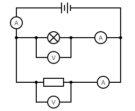
The other type of circuit is a parallel circuit. This is where there are junctions in the circuit that allow the electrons to take different routes. But the total number of electrons leaving the battery must always be equal to the total number arriving back after ‘giving up’ their energy to the circuit. This means that if you add-up the currents going down two different branches of a circuit, the number will always equal the current in the main branch that supplied the two side branches.
An example parallel circuit is shown below. It looks a bit scary but the good news is you don’t need to be able to do any calculations for parallel circuits – apart from adding up. Specifically, the current reading on the ammeter on the left of the circuit will be equal to the sum of the current readings on the two ammeters that are in the branches of the circuit. You should also know that the two voltmeters will both give the same reading and that this will be equal to the potential difference of the battery. Why? Because the leads from the voltmeters are connected straight to the battery: remember that meters don’t transfer any energy so it’s as if the ammeters aren’t there!
You might ask if there is a way to predict which way the electrons will go when they reach a junction. The answer is yes! Most of the electrons will go down whichever branch has the lowest resistance. But that will make the lower-resistance branch very conjested, so a few electrons will go down the higher-resistance branch because it is easier for them overall. The current will therefore be lowest (but not zero) in whichever branch has the highest resistance. You do not need to be able to calculate resistances in parallel circuits for the AQA Trilogy course but you do need to know that the overall effect of putting components in parallel is to reduce the overall resistance to less than the value of the smallest resistor.
