
Many GCSE Physics courses, including AQA Trilogy, include a compulsory practical to investigate the current-voltage (I-V) characteristics of various electrical components. This experiment links back to the work done by Georg Ohm, whose results have previously been summarised as; “the current flowing through a conductor is directly proportional to the potential difference (voltage) across the conductor”. For more details, read this article.
Sadly, the summary given above isn’t true for all components. That fact brings us to the practical explained here, which investigates the behaviour of three different components; a resistor, a diode and a filament lamp (the type of lamp that emits light by heating a thin, coiled wire). It is important that you are able to describe both the experiment’s method and its results
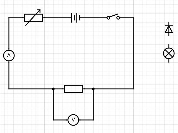
A number of different circuits can be used to carry out this investigation. One type of circuit is shown below, with a resistor installed for testing. A diode and a lamp are shown alongside and will be inserted in place of the resistor when required for testing.
https://www.circuit-diagram.org/editor/
which benefits from the correct (IEC) component symbols.
In this circuit, the power supply has a fixed voltage and a variable resistor is used to change the current that is provided to the circuit. The ammeter measures the current flowing through the component and the voltmeter measures the potential difference across the component. A table of results can be created, listing the current and voltage values for different settings of the variable resistor. These values can then be plotted on a graph (see later).
The circuit can also be built using a low-value fixed resistor in place of the variable resistor. In this case, different voltages are set on the power supply, often from 2 V up to 12 V. Once again, the ammeter and the voltmeter record the current and the potential difference for the component that is being tested. (The purpose of the low-value resistor is to limit the maximum amount of current that can flow around the circuit: this is particularly important when testing the diode.)
Note that the diode is a directional component so it must be inserted the right way around: that means with the “arrow” of the diode’s symbol pointing in the direction of the current flow. If the diode is put into the circuit the wrong way around then no current will flow. To make life easier, a light-emitting diode can be used: this is a slightly different component from a simple diode but it has similar I-V characteristics and illuminates to show that it is working correctly.
Incidentally, their “one-way” operation means that diodes are often installed in real-life circuits to protect the electronics against a user who accidentally inserts the battery (or connects the power supply) the wrong way around. If that mistake is made, the diode will block the current and therefore avoid damage being caused to the circuit.
Going back to our experiment, it’s worth noting that the values recorded are rarely “round numbers” and plotting the graphs will therefore be trickier than is the case for many other experiments that are carried out in GCSE Physics. If you use a variable power supply, you must NOT assume that the number shown on the dial is the same as the potential difference across the component: it is essential that a voltmeter is used to get an accurate reading!
Typical graphs for the three components are shown below.

If you are asked to describe these graphs, you should make statements similar to those listed below.
- The current flowing through a filament lamp increases when the potential difference increases and at low voltages the relationship is approximately linear. But at higher voltages, the current increases much more slowly than the voltage. (This is because the lamp’s resistance is increasing, due to the current causing heating, which makes it more difficult for electrons to pass through the filament wire inside the lamp.)
- The current flowing through a resistor is always directly proportional to the potential difference. Strictly speaking, this type of resistor is known as an “ohmic resistor” because it follows Ohm’s Law, as expressed at the start of this article.
- The current flowing through a diode is zero until the potential difference reaches the diode’s threshold value, after which the current increases rapidly and linearly. If a negative potential difference is applied to a diode, the current always remains at zero.
