
Focusing is the term that describes parallel rays of light being brought together into a single point, known as the focal point. Electromagnetic waves can be focused using either refraction (with lenses) or reflection (with mirrors). Both of these effects can be explored in the excellent geometric optics simulation that has just been unveiled by PhET in HTML5 form, so it should work on mobile devices as well as PCs.
In GCSE Physics courses, much more attention is given to focusing by refraction but we will first touch on reflection as it has a couple of common applications that I hope you will recognise.
Reflection is a way to focus electromagnetic (EM) waves using curved surfaces that do not introduce any change in velocity. This is the method employed in satellite dishes, where microwave TV signals are brought to a focus just in front of the dish. At the focal point, a detector receives the signals and passes them through wires to the decoder (satellite box).
Focused reflections also provide the magnifying effect that is seen when using concave mirrors (where the surface “goes inwards”). If you are very close to a magnifying mirror then you will see an enlarged view of yourself, which can be useful when applying make-up, but if you move further back the image inverts (turns upside down) and becomes much harder to see. This effect is also visible, although not as clearly, when looking at reflections in spoons. The transition from an upright view to an inverted view happens when you are at a distance from the mirror surface that is equal to the focal length of the mirror.
Lenses, on the other hand, focus light using refraction, which involves a change in speed. Remember that the word light is used to mean any sort of electromagnetic waves, not just visible light. As it happens, microwaves can be focused using refraction but the lenses used are made of wax (which is visually opaque). Infra-red waves are focused using visually transparent lenses but the focal point is slightly further from the lens than it would be for visible light because infra-red waves have a longer wavelength.
Convex lenses (with surfaces that bulge outwards) are used to produce real images: this means the image can be projected and seen on a “screen”, which might be the sensor in a camera or the retina at the back of your eye. The image is inverted so your eye actually sees the world upside-down and your brain has the job of flipping the image the right way up so that it makes sense: the same job is done by the electronics inside a digital camera. And when a data projector throws an image onto a screen, the image is inverted before projection so that is seen the right way up.
That’s as much as is required for the AQA Trilogy course but I think it’s important to extend this a bit further so that you have a basic appreciation of how simple lenses work, not least because more detail is covered in other GCSE courses and it is required knowledge for post-GCSE courses.
The important property of any lens is its focal length, which is the distance from the lens where incident parallel rays will be brought together at a point on the other side of the lens. This is shown in the diagram below.

We can use the position of the focal points on both sides of a convex lens to find the position of the image that is produced by an object placed at a certain distance in front of the lens. The method is illustrated here and explained below;
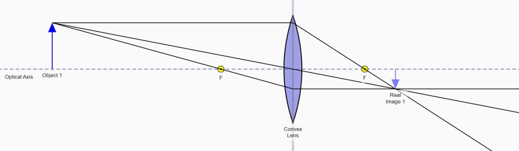
The object (labelled Object 1) is drawn to a scale such that its height is slightly less than the distance between the optical axis and the top edge of the lens. Three rays are then drawn from the top point of the object as follows;
- The first ray (the middle ray in the diagram) is drawn directly through the centre of the lens. The ray emerges from the far side of the lens with no change in direction because the symmetry of the lens means that the refraction occurring at the exit surface is exactly equal and opposite to the refraction at the entry surface.
- The second ray (the bottom ray in the diagram) is drawn diagonally through the focal point on the left-hand side of the lens to the middle of the lens. At the centre of the lens, the ray changes direction to become parallel to the optical axis and emerges from the right-hand side of the lens with no further change in direction.
- The final ray (the top ray in the diagram) is drawn parallel to the optical axis until it arrives at the centre of the lens, where it changes direction to travel diagonally through the focal point on the far side of the lens.
These three rays all converge at a point that marks the top of the image (because they originated from the top of the object). Conveniently, the object was stood directly on the optical axis so the image must be “suspended” below the optical axis. This arrangement does not have to be the case: it just makes things simpler here.
I hope it will occur to you that the second and third rays cannot have changed direction in the middle of the lens as any such effect must be due to refraction, which happens at boundaries, not inside transparent objects. Nevertheless, the construction method is correct for our purposes. If a careful scale drawing is made, taking account of the object distance relative to the focal length of the lens, then the position of the image and its height will also be accurate to the same scale.
Whereas convex lenses bring parallel light rays to a real focus on the far side of the lens, concave lenses cause the rays to diverge, as if they have originated from the focal point on the incident side of the lens, creating virtual images. We will say no more about this here as the detailed behaviour of convex lenses, let alone the complexities of concave lenses, are beyond the AQA Trilogy course.
