
Electromagnetic (EM) waves are generated by the movement of electrons. In an electric circuit, visible light can be generated when electrons (a current) move through a lamp. Electric circuits can also generate infra-red waves (TV remote controls), microwaves (ovens), x-rays (medical scanners) and radio waves (aircraft ground-to-air communications).
These different types of EM waves have different properties but they share certain behaviours, known as; reflection, refraction, absorption, transmission and emission.
Radio waves can go through walls (they are transmitted) whereas light waves can’t (they are absorbed and reflected). We can see walls and other objects because our eyes are sensitive to the electromagnetic waves that are reflected from the surfaces of those objects: if our eyes were sensitive only to radio waves then we wouldn’t be able to see most objects due to a lack of reflections! But radio waves can be reflected under some circumstances, such as at boundaries between different layers in the atmosphere, thereby allowing radio signals to propagate over very long distances, beyond the visible horizon.
The diagram below shows the basic principles of reflection: we normally assume the ray is a beam of visible light but it could be any type of EM wave that is matched to a suitable reflecting boundary. For simplicity, we’ll just use the term “light”.

Reflection from a smooth surface is symmetrical: the angle at which the light shines onto the surface (the angle of incidence) is the same as the angle at which it is reflected from the surface. We measure these angles from an imaginary line that is perpendicular to the surface: this line is called the normal. There is a great interactive tool you can use to view this symmetry at http://nasaphysics.cet.edu/reflection.html. Mirror-like reflection, where the reflected ray carries information about the incident ray (they both have the same angle) is known as specular reflection
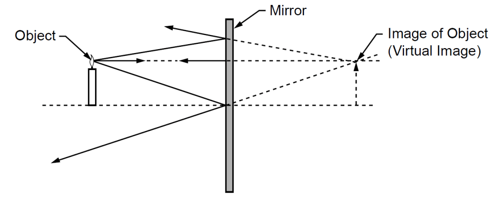
Although we often draw just one ray, in fact there are many rays of light coming from a single point on an object and these rays all follow the same law of reflection; the angle of incidence is always equal to the angle of reflection. When we look in a mirror, our eyes cannot follow the rays through their change of direction so we interpret the image as being located behind the mirror. When multiple reflected rays are traced backwards, through the mirror without including the change of direction caused by reflection, we arrive at the position of the image, which is located at the point where the rays meet, as shown below. It is known as a virtual image because it does not actually exist, whereas the image that thrown onto a screen from a data projector, for example, is a real image.
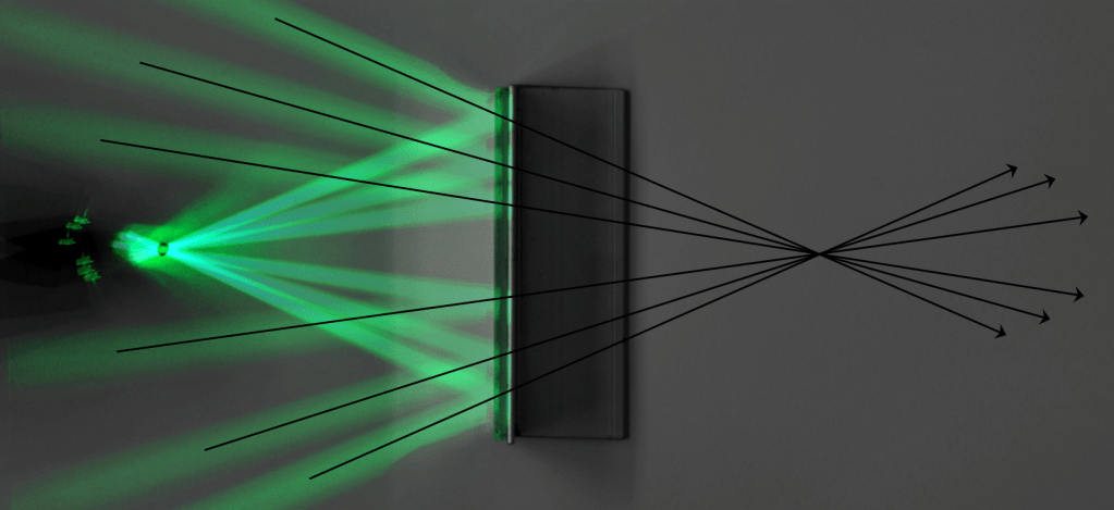
This same effect is shown below in a composite photograph taken from an experiment that you should have performed at some stage in a school science lab, possibly back in Year 8!
Note that reflection from a rough surface results in rays of light being scattered in random directions and it is this loss of order that prevents us from being able to view a recognisable reflection in rough surfaces. This type of reflection is known as diffuse reflection.
Refraction occurs when a wave crosses a boundary and involves a change in direction due to a change of speed when the wave moves from one material into another. Both materials (one of which may be the air) must be transparent to whichever type of electromagnetic wave is being refracted. The golden rule is: a light ray travels closer to the normal when moving through a medium in which its speed has been reduced.
Initial experiments to investigate the change in direction of a light ray as it crosses from the air into a plastic or glass block normally involve ray diagrams that show the light as a single line: we actually know that light is an electromagnetic wave, so that line should really be a wave. If you are sitting the Higher Tier examination, you need to be able to go further to explain, rather than just describe, refraction. These three stages of complexity are shown in the illustration below.
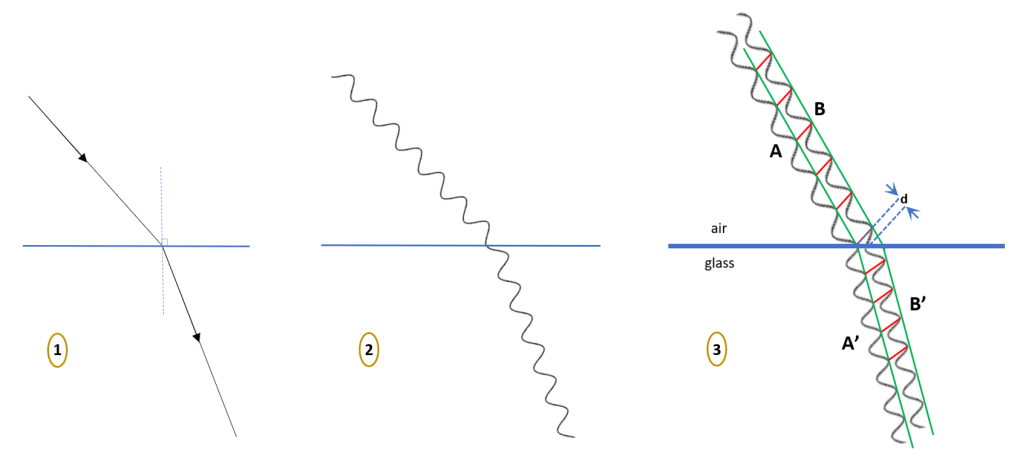
In the final part of this illustration (diagram 3) the light ray has been “magnified” to show that it has a definite width, bounded by the green lines. Short lines, drawn in red, connect the peaks on opposite sides of the light beam: these lines are known as wave-fronts and we will use this construction to explain why refraction occurs when light crosses a boundary.
The points where the wave-fronts meet the edge of the beam on the lower side, labelled A, will reach the boundary before the points where the wave-fronts meet the upper side of the beam, labelled B. The delay in distance is marked on the diagram as d. Given that light (all EM waves) travel at a very high speed (3 x 10⁸ m/s) the distance d corresponds to a very short time interval – but it is a finite time nevertheless. During this very brief time, the lower side of the wave is inside the glass whereas the upper side is still in the air. So if light moves slower in glass, the lower side of the beam will move a distance less than d during the same time as the upper side of the beam moves a distance equal to d. As a result, the beam must change direction. This change in speed, causing a change in direction, is our explanation for refraction.
Two important points to note are;
- The wave-fronts connect identical points (wave-crests) across the width of the beam both before and after refraction has occurred.
- The wave-fronts are closer together when the wave is moving slower: this means the wavelength reduces when the speed reduces.
In the real world, refraction and reflection both happen at the surface of a transparent medium but, when learning the basics, we tend to treat these two effects separately. There is a great interactive animation from PhET that allows you to explore what really happens when light meets a surface. The animation has both a ray version and a wave version – and the wave version shows a “real time” view of the changing angle and spacing of wave-fronts as they cross the boundary. It’s simple to use and very highly recommended: you can find it at https://phet.colorado.edu/sims/html/bending-light/latest/bending-light_en.html.
Select the Intro section and press the red button to activate the light source: switch between Ray and Wave views and drag the light source to different angles to observe the effects produced. When in Wave mode, the width of the reflected and refracted beams indicates the relative intensities of the two components so you should be able to get a good feel for what is happening. It really is worth exploring!
There is, of course, a mathematic expression for refraction but this is not part of the AQA Trilogy course. But it is part of other courses so it is worth saying that the expression is called Snell’s Law. There is a nice experimental approach to Snell’s Law on physicsclasroom.com or you can read a shorter explanation on savemyexams.co.uk, here. While you’re on the SaveMyExams website, it’s worth exploring the complete set of revision notes for the entire Biology, Chemistry and Physics courses within AQA Combined Sciences. Note that downloads are only available if you join the website but on-screen materials are all provided free-of-charge.
Most of this post has been about reflection and refraction because these are the two behaviours of EM waves that require detailed explanation. Other behaviours only need to be defined and described, as follows.
Absorption is the transfer of an EM wave’s energy into a physical material. This process often causes heating but it may also cause fluorescence (where a surface is seen to glow with a visible colour, despite being illuminated with invisible UV light, for example). Absorbent materials are said to be opaque but you could also think of them as having zero transmission (see later).
Emission is the release of EM waves from a material: it is often due to heating or the movement of electrons in an electric circuit. All hot objects emit EM waves to some degree, even your own body – and even when you feel very cold. Radio waves of different frequencies are emitted by oscillating electrons (moving them backwards and forwards) in the aerial at different rates, controlled by the radio’s circuitry. Note that the highest energy EM waves, gamma waves, are produced not by the motion of electrons but by changes within the nucleus of an atom: gamma waves are one of the three types of emissions that occur in radioactive decay – but they are electromagnetic waves all the same.
Combined absorption and emission can occur due to changes in the orbits of electrons in an atom. This is on the edge of the AQA Trilogy syllabus but it is included in some other courses and is definitely required for A-Level studies, so here’s a quick explanation… If we imagine electrons as being located at specific orbital distances, like lanes on a running track, then an electron can absorb energy to move to a higher orbit (away from the nucleus) and emit energy when dropping to a lower orbit (closer to the nucleus). This process happens continuously and can be used to explain why objects appear coloured: all light is absorbed on the surface of the object and only the reflected light (the colour of the object) is light emitted. It is also the process that is used to create laser beams, which have a very specific colour (a single wavelength).
Transmission is the transfer of an EM wave’s energy through a physical material. In the case of visible light, we have different words for objects that cause disruption to the information carried by the light and those that do not. If there is no disruption, an image can be viewed through the material and we say that the material is transparent: conventional windows are the obvious example. But if there is disruption to the light as it passes through the material’s surfaces, no picture can be seen and we say the material is translucent: frosted glass and tracing paper are good examples. This distinction is similar to reflections that can be either specular or diffuse, as explained earlier.

One thought on “Properties of EM Waves”