
Having covered the basics of resultant forces, we can progress to a method for analysing vectors that does not rely purely on scale drawings. Before proceeding, let me stress that this approach is not needed for GCSE Physics but the method should be accessible to mathematically inclined readers and will prove very useful in post-GCSE studies.
We will start by reconsidering the aircraft-and-crosswind situation discussed the final installment of the recent three-part series about resultant forces: the two component vectors identified in that scenario have been plotted on a grid (graph paper) in the illustration below.
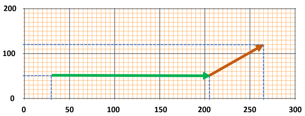
Looking at the grid, we can determine the magnitude of each vector acting in the horizontal direction (x-axis) and the vertical direction (y-axis). The green vector has zero vertical magnitude as it acts parallel to the x-axis. The green vector’s horizontal magnitude is found by determining its length on the x-axis, which is calculated (rather than measured) by subtracting the x-axis coordinates: 205 – 30 = 175.
Now let’s look at the amber vector, which has a magnitude on both the x-axis and the y-axis. The horizontal magnitude is determined by subtracting the amber vector’s x-axis coordinates: 265 – 205 = 60. Unsurprisingly, we apply the same method, using the y-axis coordinates, to determine the amber vector’s vertical magnitude: 120 – 50 = 70.
Here comes the clever bit: to determine the horizontal magnitude of the resultant, we simply add the horizontal magnitudes of the two component vectors. Likewise, to determine the vertical magnitude of the resultant, we simply add the vertical magnitudes of the two component vectors.
Therefore, the horizontal magnitude of the resultant is 235 (175 + 60) and the vertical magnitude of the resultant is 70 (because only the amber vector contributes a vertical component to the resultant).
We can then use Pythagoras’ Theorem to find the exact magnitude of the resultant by taking the square root of the sum of the squares of the horizontal and vertical magnitudes;
resultant magnitude = square root of (2352 + 702)
This gives us a resultant magnitude of 245 (to three significant figures).
Finally, we use trigonometry to determine the angle of the resultant vector, as shown in the illustration below.
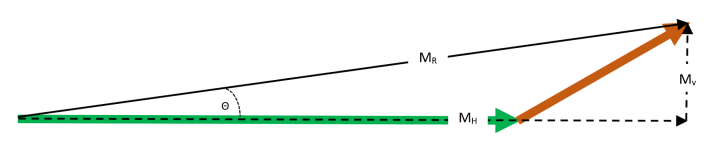
The direction of the resultant vector can be calculated using the fact that the tangent of the angle Θ is equal to the vertical magnitude (MV) divided by the horizontal magnitude (MH) as expressed in the equations below;
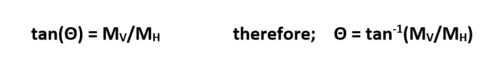
Using the numbers we obtained earlier, we can calculate the ratio to be 0.298 (70/235): this in turn allows us to determine a value of 17 ° for the angle Θ.
All of this can be combined to give exact values for the resultant vector;
- the magnitude of the resultant vector is 245
- the direction of the resultant vector is 17 ° above the horizontal (x-axis).
So, if the vectors were velocities representing a light aircraft headed due East and flying through the air at 170 km/h, the south-westerly crosswind would result in an overall ground speed of 245 km/h and a true direction of flight that is 17 ° north of due East.
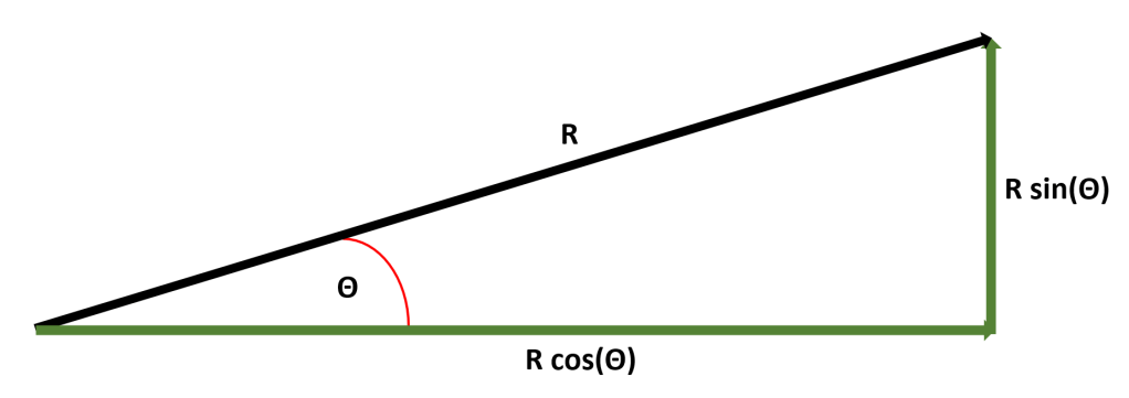
As a postscript, I should add that the initial graph-drawing stage can be omitted if the component vectors are specified with their own directions (rather than just as visual representations). In this case, the vertical and horizontal components of each vector can be calculated using trigonometry, as indicated in the diagram below.
I will stop at this stage and leave individual readers to imagine and analyse their own example scenarios. More help on this topic can be found on the A-Level Physics website.
