
In the final part of this mini-series, we have to deal with situations where the two component forces are neither opposite nor at right angles; the forces are simply at some general angle to each other.
Typical situations where this could apply in real life are tugs pulling a ship or an airplane flying through a crosswind. The illustration below shows the situation for an aircraft that wants to fly East (to the right) but has a tailwind that is both speeding it up and pushing it off course.
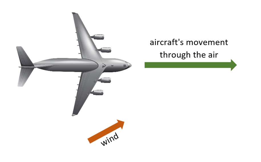
The exact direction in which the aircraft will move, relative to the ground, can determined by constructing a suitable triangle, with the two component force vectors joined nose-to-tail, but that is not what GCSE Physics examiners expect you to do: the exam board will want to see a parallelogram.
Why use a parallelogram? Firstly, we should note that a parallelogram is nothing more than a pair of triangles, formed by rotating one triangle about the mid-point along its hypotenuse. A vector parallelogram is therefore nothing more than a combination of two vector triangles.
Importantly, the parallelogram reveals that the order in which the forces are arranged in a vector triangle is irrelevant, as explained by the illustration below.
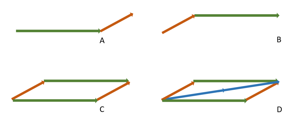
- In diagram A, the aircraft’s velocity vector has been drawn first and the wind vector has then been added to it.
- In diagram B, the wind’s velocity vector has been drawn first and the aircraft’s vector has then been added to it.
- In diagram C, diagrams A and B have been combined: it is clear that the same end point is reached regardless of the order in which the two component vectors are drawn.
- In diagram D, the resultant vector has been added.
In a GCSE Physics exam, solving a question of this type is just a matter of making an accurate scale drawing and measuring, with a rule, the magnitude of the resultant vector. And don’t forget to include the direction of the resultant as well.
Remember that vectors are only properly defined when they have a magnitude and a direction!
There is an excellent online vector animation that I strongly recommend to you. Stick to just two components and have a go at changing the vectors to discover the different resultants that can be produced. The animation is part of Walter Fendt’s collection, all of which can be accessed here.
An example use of the animation is shown below, depicting the situation where two tug boats, with different amounts of thrust (different lengths of force vector) can be angled to pull a ship forwards.
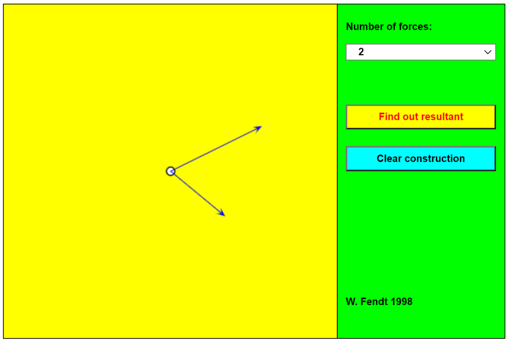
To change the sizes and directions of the component forces (shown with thin blue arrows) just click and drag the arrowheads to the desired positions. Then click on the Find Out Resultant button and watch as one of the component vectors is moved (by parallel translation) to be placed nose-to-tail with the other. The resultant is then displayed as a thick red arrow.
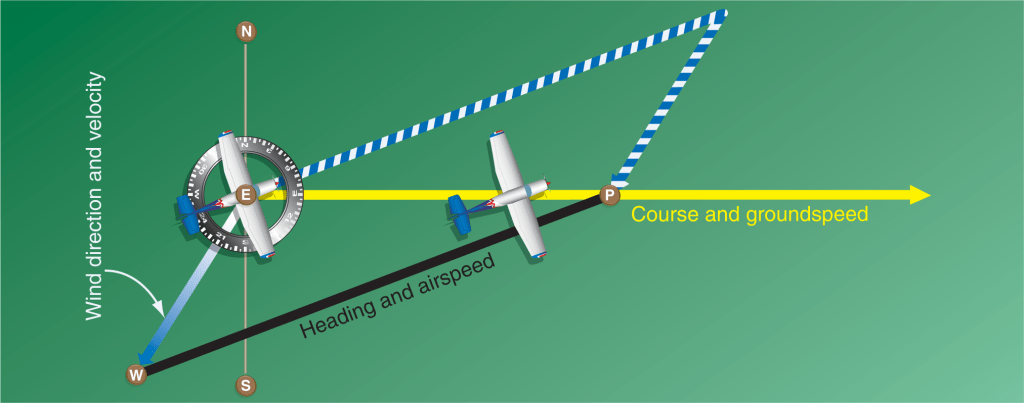
To conclude, it’s worth noting that the type of situation commonly used in GCSE Physics papers does not match real life. Aircraft pilots are expected to ensure that the aeroplane moves in the direction of the expected destination, rather than being pushed off course, and they therefore angle the nose of the aircraft to compensate for any crosswind. The real-life situation, in which the aircraft’s movement is known as crabbing, is shown in the illustration below.

One thought on “Resultant Forces (part 3)”