
The famous “electricity war” between Edison and Tesla wasn’t just about electricity generation, it was also about electricity distribution. Edison’s DC electricity couldn’t be sent very far due to power losses but Tesla’s AC could go much further and benefit people over a much wider area.
Efficient electricity distribution relies on minimising power loses due to heating of the transmission cables that carry the electricity. This in turn means the current must be kept as low as possible because power losses vary with the square of the current: dropping the current to one-tenth of its previous value therefore reduces power losses to just one-hundredth of the previous amount. Clearly, reducing power losses by 99% is a huge advantage!
In order to distribute large amounts of electricity, low currents have to be matched with high voltages (because power = current x voltage) but high voltages would be dangerous to use in homes and factories. The answer is to have high voltages for long-distance distribution then to swap to lower voltages for final use.
The voltage of DC electricity isn’t easily changed but AC electricity can be put through transformers that raise or lower the voltage as required. Transformers are therefore at the heart of modern electricity grids.
A transformer contains a pair of coils linked by an iron core. When AC electricity passes through the first coil (the primary coil) it creates a magnetic field: this is carried through the iron core to the other coil (the secondary coil) where the changing magnetic field induces a separate alternating current, as shown in the diagram below.
Note that electricity is created in the secondary coil of a transformer even though there is no electrical connection to the primary coil: the energy is transferred entirely through a changing magnetic field.
The magnetic field is changing only because the electricity source has alternating current. The changing magnetic field produces moving magnetic field lines and this is equivalent to moving a magnet past a coil of wire, which we know will produce electricity as this is the idea behind a generator, which can be thought of as a motor working in reverse.
Whereas a motor takes in electrical energy and outputs kinetic energy, a generator takes in kinetic energy and outputs electrical energy. In both cases, there is a clear link between three things; electric current, magnetic field and movement. In the case of a transformer, the movement is not mechanical but is instead created by expanding and collapsing the magnetic field due to the changing current flow.
Let’s look more carefully at what a transformer actually does.
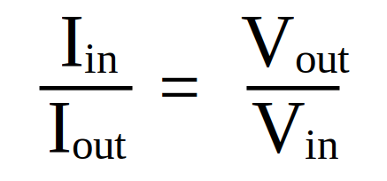
Firstly we have the conservation of energy, which says that, in an ideal transformer, the electrical energy in is equal to the electrical energy out. The energy per second is equal to the power, so we can say the power input is equal to the power output. And since electrical power is equal to current multiplied by voltage, the following must be true…
current input x voltage input = current output x voltage output
This can be written as;

But it is more helpful to rearrange the equation as;
We must remember that this is for an ideal transformer: real-world transformers dissipate energy as heat in the coils and in the core. In addition, an audible hum can sometimes be heard when standing close to old inefficient transformers due to vibrations that are created by the changing magnetic field. Modern transformers are typically about 98% efficient but for our purposes we will overlook all losses, no matter how small or large, and assume 100% efficiency in our calculations.
The value of the output voltage in the secondary coil depends on the ratio of the number of turns on the secondary compared to the number of turns on the primary coil. If the secondary coil has twice as many turns as the primary coil then the output voltage on the secondary coil will be twice the input voltage on the primary coil.
We can write this relationship as follows;

Remember that the primary coil is the input coil and the secondary coil is the output coil, so the subscript p applies to the input coil and the subscript s applies to the output coil.
Although we could combine this equation with the second form of the voltages-and-currents equation, to give three ratios in one equation, the exam board will not expect you to do this. You may, however, be asked to use either of the two equations, possibly in combination with each other.
You might be asked to do calculations using currents and voltages or voltages and numbers of turns. You may also be asked why the output (secondary) voltage or current is less than expected. In this case, you should disregard the earlier comment about ideal transformers and talk about energy that is dissipated as heat. You would not be asked how this wastage could be reduced as that level of detail is not required for this exam.
You must recognise the term “step-up” as referring to transformers that increase the voltage, often at the start of an electricity distribution grid (close to the power station) and the term “step-down” as transformers that decrease the voltage.
Step-down transformers are used not only at the consumer end of an electricity distribution grid but also in homes to drop the mains voltage (230 V) further, often to around 5 V, for charging portable electronic devices, such as smartphones. There is more information about different types of transformers and their uses on the Copper Alliance website, here, which also includes some nice self-test questions (with answers).
If you want to have a go at some example questions from previous GCSE exams then click on the link below, which will take you to a PDF document that has been created for students at the Robert Smyth Academy. The questions are intended for AQA students but the content is also relevant for our course. To access the practice questions (complete with mark-scheme) click here.
You do not need to worry about the following question in our course (or even at all, unless you want to become an electrical engineer working with transformers) but you may wonder how the actual number of turns is chosen. In theory, you could make a 10x step-up transformer by having one turn on the primary coil and ten turns on the secondary coil but that wouldn’t be a good design. More turns would be better but adding too many turns would mean making the wire very thin and that would increase the resistance, so increasing energy dissipation. If you want to learn a bit more about this, take a look at the information provided on electroniclinic.
