
Whenever a current flows through a wire, it creates its own magnetic field. This may be surprising given that copper, which is normally used for electric wires, is not a magnetic material, but it is true nevertheless. This fact was discovered almost exactly 200 years ago by the Danish physicist, Hans Christian Oersted and led to the development of probably the greatest pair of machines ever invented; the electric motor and the electric generator.
Oersted demonstrated that a magnetic field is created around a current-carrying conductor simply by placing a compass near to a wire and showing that the compass needle was deflected when the current was switch on then moved back to its normal position when the current was switched off.
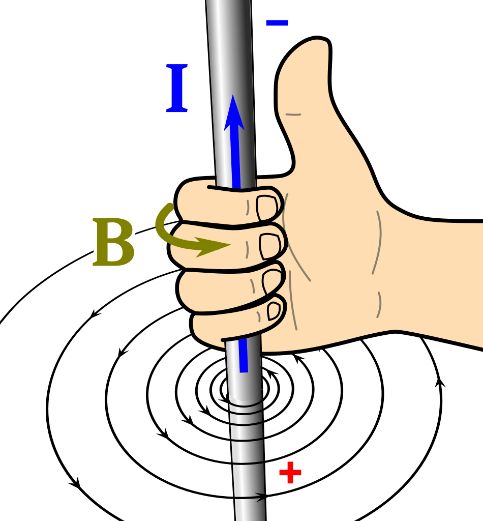
Having established a connection between the flow of an electric current and the production of a magnetic field, Oersted went on to link the direction of the current flow to the direction of the magnetic field. This link is commonly recalled using the right-hand rule (also known as the corkscrew rule) and uses a thumbs-up gesture to indicate that when the current, I, goes in the direction of the thumb, the magnetic field, B, will circle around the wire in the direction of the curled fingers, as shown below.
The same right-hand (corkscrew) rule can also be used to indicate the direction of the magnetic field inside a coil, only this time the curl of the fingers matches the direction of the loops on the coil and the thumb shows the direction of the magnetic field, as below.

Note that the magnetic field inside the coil goes from south to north whereas the magnetic field outside the coil goes from north to south, just like the field around a permanent magnet (as shown in a previous post, here). The strength of the field is weak when there is just air inside the coil but it can be increased by placing an iron bar inside the coil. Note that the iron bar is not a magnet but it becomes an induced magnet when inserted into the coil. The iron concentrates the magnetic field created by the solenoid: it does not add any extra magnetism of its own.
When an iron bar is inserted into a solenoid, the resulting arrangement is known as an electromagnet. You are expected to be able to draw the appropriate magnetic field lines for an electromagnet, which look the same as for a bar magnet (as noted above). Remember that arrows are essential on all magnetic field lines and, outside a magnet or electromagnet, they always go from the north pole to the south pole.
Like all magnetic fields, the strength of the magnetic field around a current-carrying conductor is weak when measured far away from the wire and increases with decreasing distance from the wire/solenoid. Other ways to increase the magnetic field strength are by increasing the current and, in the case of an electromagnet, increasing the number of turns on the coil.
For Higher Tier candidates only… Having looked at the magnetic fields around current carrying conductors, we can go on to see what happens when an “electric” magnetic field meets a conventional (permanent magnet’s) magnetic field.
The short answer is that when these two types of magnetic fields interact, we get a force that is capable of producing movement.
To tell the two fields apart, we focus on the direction of the current for the “electric” magnetic field. This is combined with the direction of the permanent magnet’s magnetic field to predict the direction of the force that is produced.
To get the greatest effect, the two directions must be at ninety degrees (perpendicular) to each other. In this arrangement, the direction of movement is revealed using Fleming’s Left-Hand rule, which uses the thumb, first finger and second finger of the left hand, as shown below.

https://commons.wikimedia.org/wiki/File:LeftHandRule.svg
- The thumb (“fumb”) shows the direction of the force (F).
- The first finger shows the direction of the magnetic field (B).
- The second finger shows the direction of the electric current (I).
We can use Fleming’s Left-Hand rule to predict the direction of force acting on any current-carrying conductor that is in a magnetic field. Higher-tier exam papers often test this knowledge and it is not unusual to see students twisting their hands to match a diagram shown in one of the questions!
The final step (required only for the Higher Tier paper) is to realise that we can predict not only the direction of the force but also its magnitude. This is done using the below equation, which is the simpler version of a more general equation that is not required for this course.
F = B x I x L
Force (N) = Magnetic Flux Density (T) x Current (A) x Length (m)
To generate a greater force we can increase the magnetic field strength or increase the current flowing through the wire. Alternatively, we can find a way to cram a greater length of wire into the magnetic field – and this is commonly done by winding the wire into a coil.
It is just a small step to go from using Fleming’s Left-Hand Rule with a coil of wire to get the design of a simple electric motor, in which electric energy is transferred as kinetic energy. This situation is also reversible: if we input kinetic energy, we can create movement within the motor, which then induces a current. The kinetic energy could be provided by the wind, which turns the blades of a wind turbine, for example. As a result, and quite literally, we have suddenly found a way to generate electricity out of thin air!

3 thoughts on “Electricity and Magnetism”