
There is a clear pattern to the measurements of current and potential difference (voltage) in electrical circuits – which, for us, means series and parallel circuits. These two patterns were identified by Gustav Kirchhoff and are therefore known as Kirchhoff’s Laws.
Kirchhoff’s current law states that the sum of the currents flowing into a junction in a circuit is equal to the sum of the currents flowing out of the same junction. For us, this is particularly useful when looking at junctions in parallel circuits, as shown below.
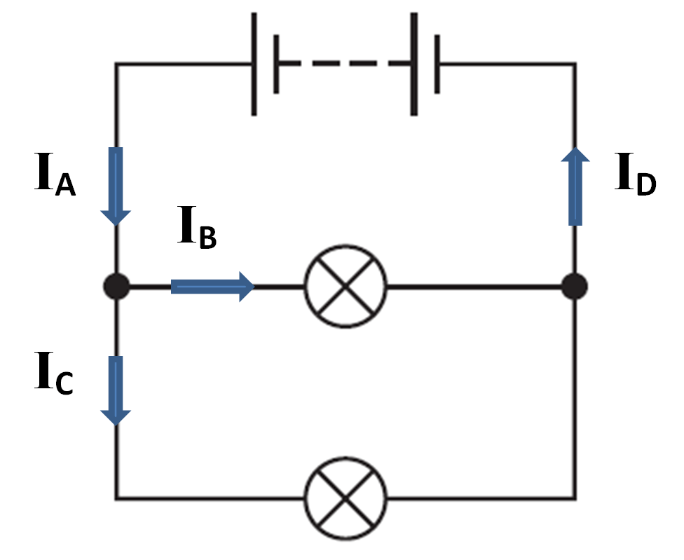
The current that is provided by the battery is given by IA and when this current reaches the junction, shown by the black dot, it divides into two separate currents IB and IC. Recalling that current has the symbol I, Kirchhoff’s current law tells us;
IA = IB + IC
Similarly, at the end of the two branches in the circuit, the two separate currents meet and combine to produce ID. This can written as;
IB + IC = ID
Comparing these two equations tells us that IA and ID must be equal. This is not surprising as it means that the current leaving the battery must be equal to the current returning to the battery.
Note that current is never “used up”: current simply carries energy around a circuit.
You can think of the electrons in a current as buckets that can be filled with different amounts of energy, which is taken to the components in the circuit. The buckets gradually get emptied (when energy is transferred) but they still return to the power supply, where they are refilled before being sent around the circuit again.
The energy that the electrons carry is measured by potential difference (voltage) and this brings us neatly to Kirchhoff’s second law, which states that the sum of the voltages around a closed loop is zero. We will apply this law to a simple series circuit, as shown below.
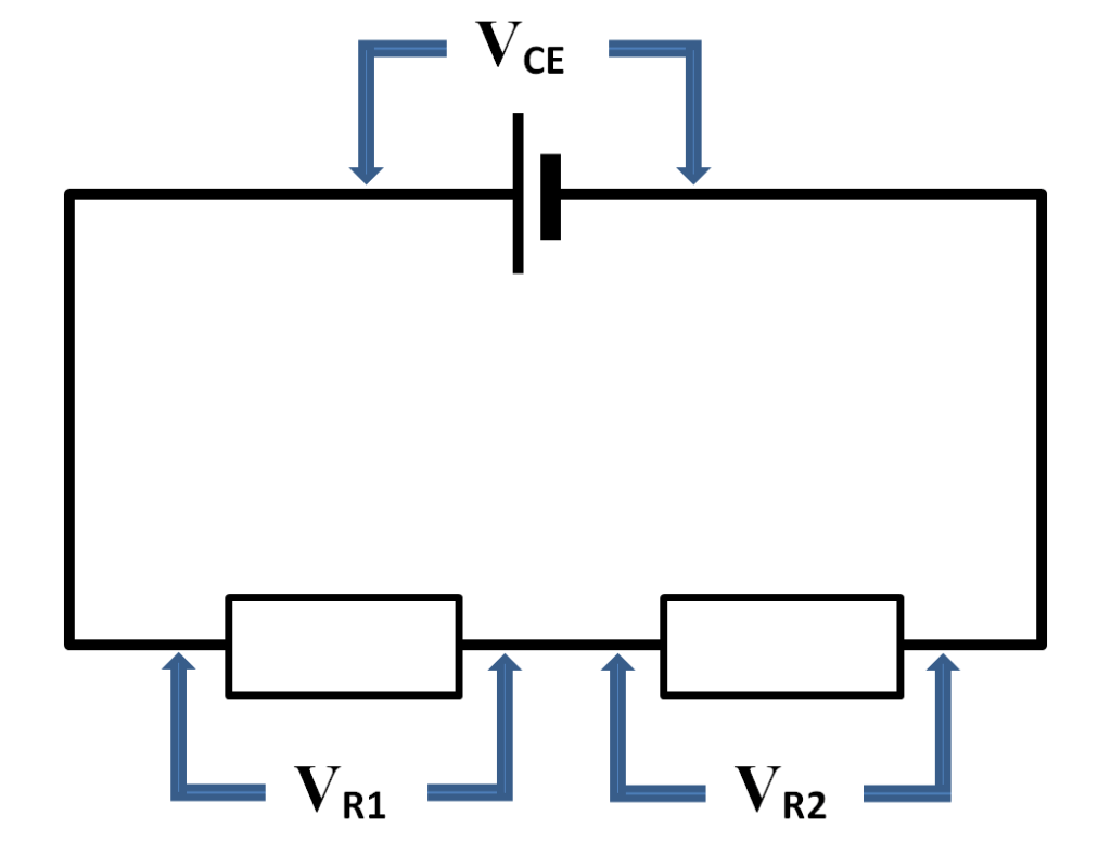
For our purposes, it is better to state the law as follows; the voltage provided by the power supply is equal to the sum of the potential differences across the components in a series circuit. This can be written as;
VCE = VR1 + VR2
This tells us that the voltage of the cell is equal to the potential difference across the first resistor added to the potential difference across the second resistor. That fact allows us to calculate the voltage across a component without measuring it – provided we know the voltages everywhere else in the same loop.
If you understand these ideas then you will be able to solve any circuit problem that you could be given in the GCSE Physics exam.
For an alternative explanation, which uses the analogy of water flowing through hoses that split at a T-junction, see this page on the Electrical Classroom website.
There is also an excellent 10-minute animation from Eugene Khutoryansky that illustrates the link between voltage, energy and current in electrical circuits: I highly recommend this animation, which you can view on YouTube, here.
